DEMOLITION OF
TOWNSVILLE WATER SUPPLY INFRASTRUCTURE
DURING WWII
![]()
The Australian Army's 5th Division developed extensive Demolition Plans to destroy the water supply infrastructure in the Townsville area during WWII to deny its use to the enemy should an invasion become imminent. The following are some excerpts from those detailed plans.
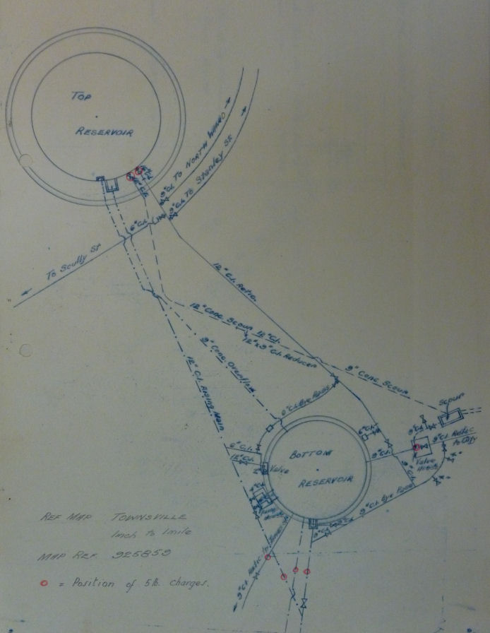
Plan:- NAA via Graham McKenzie-Smith
Demolition Plans for two Reservoirs (Water
Tanks) on Castle Hill
above Sturt Street showing the positions of 5 lb charges.
|
DRAFT OF PROPOSED OPERATION ORDER
INFORMATION. 1. The location of the Weirs and River Pumping Stations are shown on Appendix No. 2. 2. Detail on the mains and valves at the two reservoirs on Castle Hill is shown on Appendix No. 3. 3. General remarks regarding the Weirs, River Pumping Stations and Reservoirs and method of attack are given in appendix No. 1. INTENTION. The water retained and stored by Weirs and Reservoirs will be released, and River Pumping Stations so destroyed, that their use is denied to the enemy. METHOD. 1. Preparation for demolition and destruction will be made by 16 Bn. V.D.C. in accordance with METHOD OF ATTACK Appendix No. 1, and “Demolition Abstract” Appendix No. 4. 2. The C.R.E. will provide a portable magazine and the necessary explosives. This magazine will be located at the “Huberts Well Pumping and Power Station” Ref. Map TOWNSVILLE 1 inch to 1 mile – Map Ref. 894815. 3. Orders for demolition will normally be issued to Bn. Cmd. or (Group Comd.?) by G.O.C. 5 Aust. Div., or by Military Commander operating in the area. 4. Results of demolition will be reported to C.R.E. 5 Aust. Division. The orders will be issued in the following sequence:- (a) Warning Order –
On receipt of this order the V.D.C. “Demolition Party” will be assembled at the Huberts Well Pumping and Power Station, and necessary stores, explosives and equipment will be collected and distributed, and parties detailed to tasks. Explosive charges will be made up, safety fuse will be cut to required lengths, and detonators crimped to fuse. (b) Preparation Order –
On receipt of this order, parties will move to their respective tasks, with the exception of the Party detailed to destroy the “River Pumping Stations”. Charges will be placed in position. (c) Execution of Demolition Order –
On receipt of this order, the Party detailed to destroy the “River Pumping Stations” will then proceed to carry out their task in accordance with para. 3, Appendix No. 1. The “Flood Gates” in the weirs will be opened, and operating mechanism destroyed as in para. 2, Appendix No. 1. The explosive charges laid at the Reservoirs on CASTLE HILL will be fired. ADMINISTRATION The O.C. V.D.C. “Demolition Party” will make arrangements to procure the necessary transport, tools and stores, as shown in “Demolition Abstract”, Appendix No. 4. He will also prepare necessary details of organisation for the assembly of his “Demolition Party”, and the execution of their tasks. This “Demolition Party” will be trained, and personnel detailed for their various assignments. The C.R.E. 5 Aust. Division will provide technical instruction and advice, if required. INTERCOMMUNICATION Headquarters of the “Demolition Party” after “Warning Order” will be at Huberts Well Pumping and Power Station. Messages will be sent to Commander of “Demolition Party” by telephone and Despatch Rider.
Signed at __________________ hrs. …………………………….
|
|
APPENDIX No. 1 DEMOLITION PLAN – WATER SUPPLY – TOWNSVILLE Ref. Map TOWNSVILLE 1 inch to 1 mile GENERAL REMARKS AND METHOD OF ATTACK
1. WATER SUPPLY. (a) Water is conserved in the ROSS RIVER by three Weirs – Black’s School Weir, Gleeson’s Weir and Alpin’s (sic Aplins) Weir. (b) This water may be pumped from ten (10) Pumping Stations situated on the left bank of the ROSS RIVER, (details para. 3) and delivered to cisterns or wells, at the HUBERT WELLS PUMPING AND POWER STATION. (TOWNSVILLE CITY COUNCIL – POWER STATION). (c) Water may also be pumped from three wells, known as Lowth’s, Powell’s and Wilmetts Wells. At this point the water is run through filter beds, spray ponds, treated, and then pumped through two (2) 16 inch mains, by 4 electrically driven, centrifical pumps, to two reservoirs on CASTLE HILL. 2. WEIRS. (see Appendix No. 2) (a) Complete destruction of the weirs would be a difficult and costly proposition. If the water was released by means of the “Flood Gates” and their operating mechanism damaged, to prevent them being closed, the reservoirs would empty in approx. 2 days. This would not deny the enemy water, plentiful supply of which will be retained in the sand bed of the river. The next rains, sufficient to restock the reservoirs, are not expected until the end of January, 1943. (b) BLACK’S SCHOOL WEIR. (Map Ref. 846787) Hollow construction, built up of 18” reinforced concrete buttresses, covered with 24” reinforced concrete slabs. The river at this point is approx. 500 feet wide, and the weir holds back approx. 650,000 gals. This could be released through a 6’ x 6’ flood gate, and would empty same in approx. 2 days. Access to the flood gate in this weir, is through a manhole on the N.W. end, or through holes in the downstream face, on the S.W. end. A concrete platform runs through the buttresses, and the opening mechanism is on the upstream side of this platform. This mechanism has been recently oiled and greased, but the gate has not been opened for 5 years, and it may be jammed, therefore, at least 10 M.T. jacks should be provided to assist the opening mechanism. The chains and handles, needed to operate this mechanism are stored in the Pump Well on the N.W. end of the weir. METHOD. Loosen off packing glands on guide spindle and raise Gate. After the gate has been raised to its fullest extent, the “Guide Spindles” will be damaged by placing 2 lbs. of Gelignite on each, approx. 1 foot from the bottom. This charge, when fired, will bend the spindles and prevent the gate from closing. (c) GLEESON’S WEIR (Map Ref. 860788) Solid concrete wall approx. 12’ at base and 3’ at top. Width of river approx. 400 feet. – Capacity 50,000,0000 gals. – Water controlled by four 3’ x 3’ flood gates – could be emptied in approx. 2 days. The flood gates in this weir are located in chambers, built out from the upstream face of the weir. The operating mechanism is accessible from the top of the weir. The Key spanners used for opening these gates are stored at the Huberts Well Pumping and Power Station. METHOD. Open gates, and then destroy spindles with 2 lbs. Gelignite. The spindles will be attacked at a point approx. 2 ft. below the concrete platform. (d) ALPIN’S WEIR (sic Aplin’s Weir) (Map Ref. 900805) Low, concrete wall, designed to prevent the salt water from backing up the river. - Little surface water is retained by this weir. - Most of the water is retained in the sand in this section. - Flood gates not provided. METHOD. If time and circumstances permit, this weir will be destroyed by means of a mine charge, place in a coffer-dam against the upstream face of the weir. Details will not be included in this Plan, as it is intended to treat this as a “Secondary Task”. 3. PUMPING STATIONS. (See Appendix No. 2) (a) There are ten (10) pumping stations, which can be used for drawing water from the weirs on Ross River. (b) These are located on the left bank of ROSS RIVER at Map Refs. 895802, 887799, 876801, 860789, 847792, 844788, 837777, 843722, 842682, 845675. The pumps are centrifical, and are direct coupled to Elect. motors or diesel driven. At Map Refs. 842682, 845675, the pumps and motors have been removed, but the pipe fittings etc. remain. A Diesel driven pump has been installed at Gleeson’s Weir – Map Ref. 860789, and another is being installed at Map Ref. 895802. METHOD. The pump, motors and fittings could be affectively damaged by sledge hammers. 4. RESERVOIRS. There are two (2) reservoirs situated at CASTLE HILL Map Ref. 925859. These are built of concrete, and the “top reservoir” has a capacity of 1 Ľ million gallons, and the “bottom reservoir” a capacity of ľ million gallons. “Inlet” and “Outlet” valves and mains are shown on Appendix No. 3. The reservoirs could be demolished by mine, or depth charges, but this would entail much preparation, and a large quantity of explosive. The reservoir pumps at the “Hubert Wells Pumping Station” will be destroyed, and without these pumps, water cannot be pumped to these reservoirs. Therefore sufficient damage would be caused by destroying the “inlet” and “outlet” valves and mains, and so release the water. METHOD. Valves and mains to be attacked at the points indicated on Sketch 1, Appendix No. 3. 5 lb. Charges of Explosives to be used at each point. 5. WELLS. “Bone oil”, or any other available oil, together with a small explosive charge, will be used to contaminate the wells, should the necessity arise.
|
ACKNOWLEDGEMENTS
I'd like to thank Graham McKenzie-Smith AM for his assistance with this web page.
Can anyone help me with more information?
"Australia @ War" WWII Research Products

|
|
© Peter Dunn 2015 |
Please
e-mail me |

This page first produced 20 September 2021
This page last updated 21 September 2021

